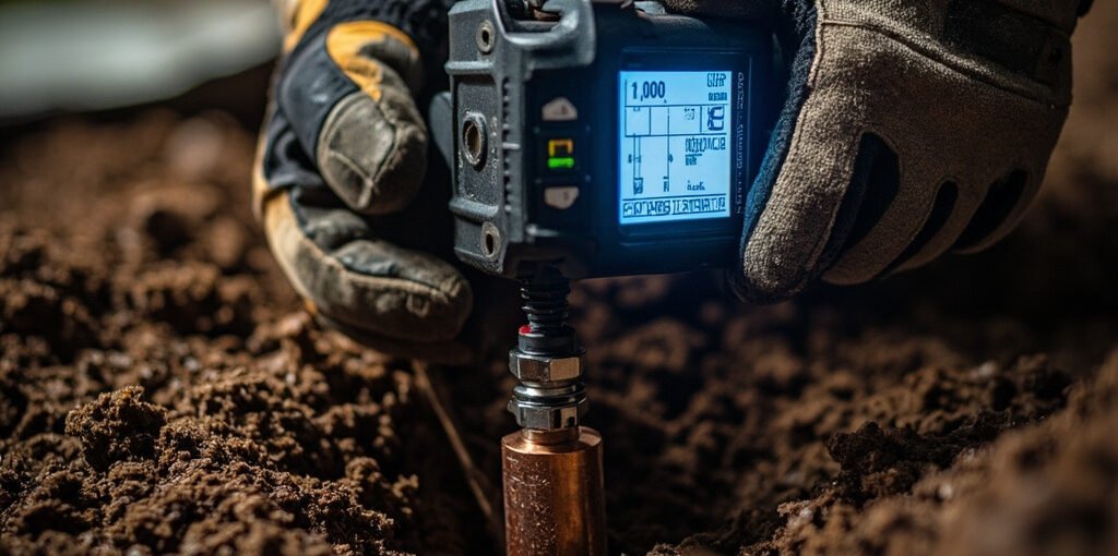
Ground resistance testing is a critical electrical measurement procedure used to determine the effectiveness of a grounding system. Whether in industrial facilities, commercial buildings, telecommunications sites, or residential installations, a properly functioning grounding system protects equipment, ensures personnel safety, and prevents costly downtime. This comprehensive guide explains what ground resistance testing is, why it matters, the methods used, the equipment required, and best practices to achieve accurate and reliable results.
What Is Ground Resistance Testing?
Ground resistance testing measures the resistance between a grounding electrode (such as a ground rod, ground plate, or ground grid) and the surrounding earth. The measurement, expressed in ohms (Ω), indicates how effectively stray electrical currents can dissipate into the soil. Lower resistance values mean better grounding performance. Standards such as IEEE 80, NFPA 70 (NEC), and IEC 62561 typically require resistance values below 5 ohms for most commercial and industrial systems, and sometimes as low as 1 ohm for substations and sensitive electronic facilities.
Why Ground Resistance Testing Is Important
- Personnel Safety: Prevents dangerous touch voltages and step potentials during fault conditions.
- Equipment Protection: Reduces damage from lightning strikes, surges, and short circuits.
- Code Compliance: Meets national and international electrical safety standards.
- System Reliability: Ensures protective devices like breakers and relays operate correctly.
- Lightning Protection: Provides a low-impedance path for lightning discharges.
- Signal Integrity: Minimizes electromagnetic interference (EMI) in sensitive electronic systems.
Common Methods of Ground Resistance Testing
1. Fall of Potential (Three-Point) Method
The Fall of Potential method is the most widely used and accurate technique, considered the standard reference test. Two auxiliary ground stakes are placed in a straight line from the electrode under test. A test current is passed between the electrode and the far stake, while voltage is measured between the electrode and the middle stake. Resistance is calculated using Ohm’s law. To obtain accurate results, the middle stake should be positioned at approximately 62% of the distance between the electrode and the far stake.
2. Clamp-On Ground Resistance Test
The Clamp-On method uses a specialized clamp that simultaneously induces a voltage and measures current through a ground conductor. It does not require disconnecting the grounding system or driving auxiliary stakes, making it ideal for urban environments or systems with multiple parallel grounds. While convenient, this method cannot be used on isolated grounds and is less accurate for very low values.
3. Selective Method
The Selective method combines the fall of potential technique with a clamp. It allows technicians to measure the resistance of a specific grounding electrode in a parallel grounding system without disconnecting it, providing both accuracy and convenience.
4. Soil Resistivity Testing (Wenner Method)
Before installing a ground electrode, the Wenner Four-Point method is used to measure soil resistivity. Four equally spaced probes are driven into the earth, and a test instrument applies current between the outer probes while measuring voltage between the inner probes. Results help engineers design grounding systems suited to local soil conditions.
Equipment Required for Ground Resistance Testing
| Equipment | Purpose | Typical Specifications |
|---|---|---|
| Ground Resistance Tester | Primary measurement instrument | 0.01 Ω – 2000 Ω range |
| Auxiliary Ground Stakes | Current and potential electrodes | Copper or galvanized steel, 30–60 cm |
| Test Leads | Connections between tester and electrodes | Insulated, color-coded, 20–50 m |
| Clamp-On Ground Tester | For non-intrusive testing | 0.1 Ω – 1500 Ω range |
| Soil Resistivity Meter | Wenner four-point testing | Four-terminal design |
Step-by-Step Ground Resistance Testing Procedure
- Visual Inspection: Examine all grounding connections, conductors, and electrodes for corrosion, damage, or loose fittings before testing.
- Isolate the Electrode: Disconnect the grounding electrode from the system under test to avoid parallel paths that could distort readings.
- Position Auxiliary Stakes: Drive two auxiliary stakes in a straight line at recommended distances (typically 20 m and 40 m, depending on electrode size).
- Connect Test Leads: Attach the leads from the instrument to the electrode under test and to each auxiliary stake following the color code.
- Take Measurements: Run the test and record the resistance value. Repeat the test with the potential stake at multiple positions (e.g., 50%, 60%, 70% intervals) to confirm a stable reading.
- Verify and Document: Confirm the reading falls within the prescribed limit, document the results, and reconnect the electrode to the system.
Recommended Ground Resistance Values
| Application | Maximum Resistance (Ω) | Reference Standard |
|---|---|---|
| Residential Electrical System | 25 Ω | NEC 250.56 |
| Commercial / Industrial | 5 Ω | IEEE 142 |
| Substations | 1 Ω or less | IEEE 80 |
| Telecommunications | 5–10 Ω | TIA-607 |
| Lightning Protection | 10 Ω | NFPA 780 |
Common Mistakes to Avoid
- Incorrect probe spacing leading to inaccurate readings.
- Failing to isolate the grounding electrode from the rest of the system.
- Testing in dry or frozen soil, which produces artificially high values.
- Poor contact between test leads and electrodes due to dirt or corrosion.
- Ignoring stray currents from nearby electrical equipment that can affect results.
Best Practices for Accurate Ground Resistance Testing
Categories

-
How to Master Technology trends in manufacturing in 2026
August 18, 2026-
-