Selecting the right harmonic drive (also known as a strain wave gear) is a critical engineering decision that directly impacts the precision, efficiency, and longevity of motion control systems. Used extensively in robotics, aerospace, medical devices, semiconductor manufacturing, and machine tooling, harmonic drives offer unmatched torque density, zero backlash, and exceptional positioning accuracy. However, choosing the optimal unit requires a deep understanding of application requirements, mechanical constraints, and performance trade-offs. This comprehensive guide walks you through the essential parameters, selection criteria, and best practices to ensure you specify the perfect harmonic drive for your project.
What Is a Harmonic Drive?
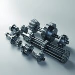
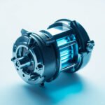
A harmonic drive is a specialized gear mechanism that operates on the principle of elastic deformation. It consists of three main components: a wave generator (input), a flexspline (output), and a circular spline (fixed). The wave generator deforms the flexspline into an elliptical shape, which engages with the circular spline to produce motion with gear reduction ratios typically ranging from 30:1 to 320:1. Because of this unique design, harmonic drives provide compact size, high reduction ratios in a single stage, and inherent zero-backlash performance.
Key Specifications to Evaluate
Before comparing models, you must clearly define the load profile and duty cycle of your application. Below are the most important specifications engineers should analyze:
- Rated Torque: The continuous torque the drive can transmit without exceeding thermal limits.
- Peak / Emergency Torque: The maximum short-duration torque during shock loads or acceleration.
- Backlash: Typically less than 1 arc-minute, with some models offering zero backlash.
- Hysteresis Loss: Energy lost due to flexspline deformation—important for high-cycle applications.
- Repeatability: Usually within ±0.5 to ±2 arc-minutes depending on size and quality.
- Lifetime: Rated in hours or revolutions under specific load conditions.
- Efficiency: Typically 65–85% per stage, decreasing with ratio and load.
Harmonic Drive Selection Criteria
The selection process should follow a structured methodology rather than a simple “best-spec” approach. Use the following framework to narrow your options:
- Define the application profile: Identify whether the drive is used in robotics (high dynamic), CNC (high precision), or aerospace (low weight, high reliability).
- Calculate effective torque: Include safety factors (typically 1.5–2.0) and account for peak, continuous, and reversing loads.
- Determine reduction ratio: Higher ratios deliver more torque but reduce efficiency and speed.
- Consider environmental factors: Temperature range, vacuum compatibility, cleanroom requirements, and exposure to contaminants.
- Evaluate mounting options: Shaft, flange, hollow, or integral servo motor configurations.
- Review life expectancy requirements: For 24/7 industrial use, you may need premium lubrication systems and oversized units.
Comparison of Common Harmonic Drive Types
The table below compares three widely used harmonic drive series to help you visualize the trade-offs between size, torque, and precision:
| Feature | Standard Series | Precision Series | Miniature Series |
|---|---|---|---|
| Diameter Range | 50–300 mm | 40–250 mm | 10–30 mm |
| Rated Torque | 5–2,000 Nm | 3–1,500 Nm | 0.1–10 Nm |
| Backlash | ≤ 1 arc-min | Zero backlash | ≤ 2 arc-min |
| Reduction Ratios | 30:1 to 160:1 | 50:1 to 200:1 | 30:1 to 100:1 |
| Typical Use | Robotics, CNC | Semiconductor, optics | Medical, drones |
Sizing Methodology: A Step-by-Step Approach
Properly sizing a harmonic drive is essential to prevent premature wear and ensure long-term reliability. Follow this proven methodology:
- Calculate the equivalent output torque using the duty cycle and average load.
- Apply a service factor of 1.25 for uniform loads, 1.5 for moderate shock, and 2.0 for heavy shock.
- Compare the result to the manufacturer’s rated torque at the target speed.
- Verify peak torque does not exceed the drive’s instantaneous rating.
- Check thermal limits—ensure continuous losses do not raise internal temperature beyond 80°C.
- Validate life expectancy by comparing calculated L10 life with design requirements.
Common Mistakes to Avoid
Even experienced engineers sometimes overlook critical details. Avoid these frequent errors:
- Ignoring torsional rigidity: A high reduction ratio cannot compensate for low stiffness in precision applications.
- Overloading during emergency stops: Sudden deceleration can generate torque spikes far above rated values.
- Skipping lubrication analysis: Standard grease may fail in vacuum or extreme temperatures; specify synthetic or solid-film lubricants accordingly.
- Mismatching input speed: Exceeding rated input RPM causes wave generator wear and rapid failure.
- Neglecting alignment: Misalignment between motor and drive introduces radial loads that drastically reduce life.
Lubrication and Maintenance Considerations
Proper lubrication is fundamental to harmonic drive performance. Most manufacturers pre-fill the unit with high-grade synthetic grease, but operating conditions may require re-lubrication intervals between 5,000 and 20,000 hours. In cleanrooms or vacuum environments, consider dry-film or perfluoropolyether (PFPE) lubricants. Always follow the manufacturer’s service schedule and inspect seals periodically to prevent contamination ingress.
Final Thoughts on Harmonic Drive Selection
Choosing the right harmonic drive is a balance of torque capacity, precision, speed, life, and cost. By systematically analyzing your application’s load profile, duty cycle, and environmental conditions—and by applying proper service factors—you can confidently select a unit that delivers years of reliable, high-precision performance. Whether you’re designing a six-axis robot, a satellite positioning system, or a surgical robot, the principles outlined above will help you make a sound engineering decision and avoid costly redesigns down the road.