When replacing an unknown motor, understanding the nameplate markings is crucial for selecting the right replacement and ensuring compatibility with your system. This article will guide you through interpreting IEC and NEMA motor nameplates, helping you calculate key parameters like required current, power, and cooling capacity while avoiding costly mismatches.
What a Mismatched Replacement Costs
Choosing the wrong motor based on an incorrect interpretation of nameplate data can lead to several failure modes, each with significant cost implications. If the voltage rating does not match the supply, the motor may draw excessive current, blowing fuses or tripping breakers, and potentially damaging the windings through overheating. A mismatched frame size can cause mechanical stress, leading to bearing failure and shaft misalignment. If the motor’s insulation class is insufficient for the operating temperature, the insulation can degrade prematurely, resulting in short circuits and motor failure. Additionally, an incorrect service factor or duty type can cause the motor to overheat during continuous operation, reducing its lifespan and increasing maintenance costs. Understanding these risks underscores the importance of accurate nameplate interpretation.
The Four Markings That Drive Every Other Decision
Four values decide almost everything else, so read them first: rated power, rated voltage and connection, rated full-load current, and duty type. The rest refine the choice.
Power Rating: kW Against HP
Power (HP) = Power (kW) x 1.341
A 15 kW machine is nominally a 20 HP machine. The conversion identifies a replacement, but delivered power depends on frame and speed, so match kW and pole count together rather than trusting a converted number.
Voltage, Frequency and Connection
Dual-voltage IEC plates read as two figures where the second is sqrt(3) times the first: 400/690 V. The winding is designed for the lower figure, so the lower voltage is the delta connection and the higher voltage is the star connection. On a 400 V supply a 400/690 V motor runs in delta; the same machine on 690 V runs in star. Reverse that and full line voltage sits across a winding rated for the phase value, and the motor draws several times its magnetising current on no load.
A NEMA plate reading 230/460 V is a different convention: the change is made at the terminal links, not by swapping star for delta. Read the wiring diagram on the plate before touching anything.
Full Load Current
The plate current is the answer to a calculation that already includes the motor’s own losses:
FLC = (P x 1000) / (sqrt(3) x V x power factor x efficiency)
For a 15 kW machine on 400 V at a power factor of 0.85 and an efficiency of 0.90 that gives 15000 / (1.732 x 400 x 0.85 x 0.90) = 28.3 A, which is the figure printed on a modern IE3 plate. Use the printed current for protection settings rather than recomputing it, because the plate reflects that specific design.
Service Factor
A service factor of 1.15 means the machine may carry 115 % of rated output at rated voltage and frequency within its thermal limits. On a NEMA plate that is a permitted continuous duty; on an IEC plate the equivalent allowance is usually not published, so treat 1.0 as the ceiling unless the maker says otherwise. What no service factor covers is a high ambient, a low supply voltage or a duty cycle the plate was not rated for. Those consume the same thermal margin from the other side.
Worked Example: A 15 kW Plate
Power 15 kW, 400 V delta, FLC 28.3 A, 1470 rpm, service factor 1.15, IP55, IC411, class F insulated to a class B rise, S1 duty. From those markings: the feeder and overload are built on 28.3 A, the starter is direct-on-line capable, the enclosure suits an outdoor washdown-adjacent position, the cooling depends on a fan on the shaft, and the duty says it may run to thermal equilibrium indefinitely.
Insulation Class Against Temperature Rise
The insulation class names the temperature the winding material is proved to withstand: 105 C for class A, 120 C for E, 130 C for B, 155 C for F and 180 C for H, all referenced to a 40 C ambient. The permitted temperature rise is a separate and tighter number, which is why a Class F machine is commonly proved to a Class B rise of 80 K. The gap is deliberate: it covers the hot spot in the middle of the winding, the tolerances, and the losses a dirty frame adds.
The substitution consequences are practical. Replacing a Class F machine with one using Class B materials in the same enclosure removes the thermal headroom. Raising the site ambient from 40 C to 55 C removes 15 K more. A motor coupled to a gearbox it was never intended for, or one with a blocked fan cover, spends the rest without any electrical change at all.
Thermistors change the picture. Where the plate lists a PTC trip point, the insulation is being protected by an embedded sensor and a trip relay rather than by a feeder overload, and that is the combination that makes long low-speed running survivable.
What Each Marking Changes in the Selection
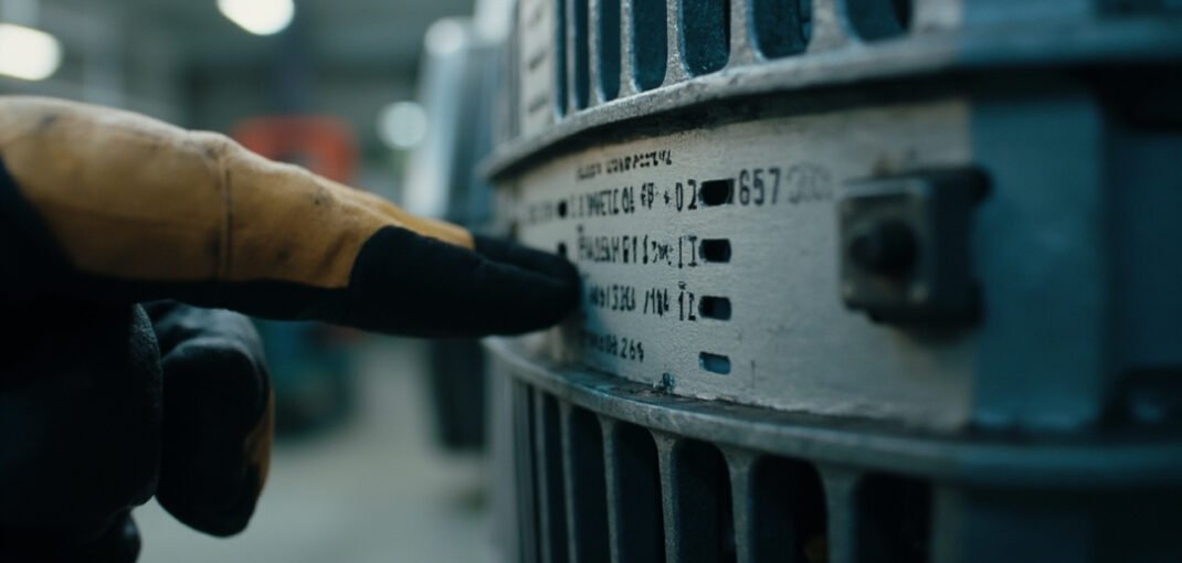
The table is the one to take to the store with the old motor photographed.
| Marking | Example | What it decides on the replacement |
|---|---|---|
| Frame and mounting | IEC 160L, B3 | Footprint, shaft height, shaft diameter, cover positions |
| Rated power | 15 kW | Whether the machine carries the load; must meet or exceed |
| Voltage and connection | 400/690 V, delta/star | Terminal links, and the magnetising current if wrong |
| Full-load current | 28.3 A | Cable, overload setting, contactor and fuse sizing |
| Speed and pole count | 1470 rpm, 4-pole | Output speed, starting torque and the duty it can survive |
| Duty type | S1, S2, S3 40 % | Permitted run and rest pattern |
| Insulation and rise | F insulated, B rise | Headroom above ambient and what a substitution costs |
| IP and IC code | IP55, IC411 | Whether it survives the site and sheds its heat |
| Efficiency class | IE3 | Losses, heat, and compliance with local rules |
| Bearing designation | 6309 C3 | Reorder part, fit, and the relubrication route |
| Thermistors | PTC 130 C | Whether inverter or low-speed duty is protected |
Duty Type From S1 to S3 in Plain Terms
S1 is continuous running to thermal equilibrium: the machine gets hot and stays there. S2 is short-time running that never reaches equilibrium, and an S1 motor of the same power is not automatically a substitute. S3 is a repeating cycle expressed as the on-time fraction: an S3 40 % machine at rated power runs four minutes in ten. A motor specified S1 but operated on a heavily cyclic duty accumulates thermal cycling that attacks the winding at the slot ends, which is why the duty line deserves to be read before the power line.
Efficiency Class IE1 to IE4
IE1 is standard, IE2 high, IE3 premium and IE4 super premium efficiency, with IE5 now appearing on synchronous reluctance and permanent magnet designs. The classes are minimum full-load efficiency levels assessed at 50, 75 and 100 % load. Higher classes generally mean more copper and better steel rather than a different frame, and the loss difference shows up as less heat in the winding and a longer insulation life. Where local regulation sets a minimum class, buying below it is not an option at all.
IP and IC Codes
The first IP digit rates solid ingress from 0 to 6, the second liquid ingress from 0 to 9K. IP55 is dust-protected and jet-sprayed, which is the usual outdoor answer; IP66 closes both further, and IP69K is the washdown rating. The IC code says where the cooling energy comes from. IC411 is a self-ventilated totally enclosed machine, with a fan on the shaft. IC416 is the same enclosure with an independently powered blower, and it is what you specify when the motor will run slowly for long periods. Read the IC code before accepting a substitution, because the fan cover that goes with it is what makes the duty work.
Fitting and Commissioning the Replacement
Proper installation is crucial for motor performance and longevity. Follow these steps:
- Verify Nameplate Data: Ensure the motor’s nameplate data matches the application requirements.
- Check Mounting: Install the motor on a stable, level surface to prevent vibration and misalignment.
- Electrical Connections: Connect the motor according to the nameplate voltage and connection diagram. Use appropriately rated cables and connectors.
- Grounding: Ensure the motor is properly grounded to prevent electrical hazards.
- Starting Method: Select the appropriate starting method (direct-on-line, star-delta, soft start, etc.) based on the motor’s full load current and application requirements.
- Commissioning: Start the motor and monitor its performance. Check for abnormal noise, vibration, or overheating.
- Load Testing: Apply the rated load and verify the motor’s performance. Measure current, voltage, and temperature to ensure they are within acceptable limits.
Field Signs of a Motor That Was Wrong
Symptom and Usual Suspect
- Overheating: Indicates excessive load, poor ventilation, or incorrect voltage.
- Vibration: Suggests misalignment, unbalanced rotor, or mechanical resonance.
- Noise: Can be due to bearing wear, loose components, or electrical issues.
- Tripping: Frequent breaker trips may indicate short circuits, overloads, or ground faults.
Ordered Checks
- Check Electrical Supply: Verify voltage and current levels; ensure they match the nameplate specifications.
- Inspect Mechanical Components: Look for signs of wear, misalignment, or damage.
- Monitor Temperature: Use a thermal camera to identify hot spots; ensure the motor is not operating above its rated temperature.
- Analyze Vibration: Use a vibration analyzer to diagnose mechanical issues; check for loose bolts or bearings.
- Review Maintenance Records: Identify any recurring issues or patterns; ensure regular maintenance is performed.
What Must Match and What May Move
When replacing a motor, certain nameplate values must match the original to ensure proper operation and safety, while others can be more flexible depending on the application. The power rating, whether expressed in kilowatts (kW) or horsepower (HP), is critical and must match or exceed the original motor’s rating. This ensures the motor can handle the load without overheating or operating inefficiently. Similarly, the voltage rating must match the supply voltage to prevent damage to the motor windings and ensure optimal performance. For dual voltage motors, verify the connection configuration is set correctly based on the supply voltage.
The full-load current is not a selection input in the same way as power, since it varies between designs, but it is the figure the cable and the protection are built on, so take it from the new plate rather than carrying the old one across. The service factor (SF) should also be considered; it indicates the motor’s ability to operate beyond its rated power. A replacement motor with a similar or higher service factor is advisable to maintain operational flexibility.
Insulation class and temperature rise are important for motor longevity and safety. The insulation class must meet or exceed the original motor’s specification to ensure the motor can withstand the operating temperature. For instance, a Class F insulation system is designed for a maximum temperature of 155°C, whereas Class B is rated for 130°C. If the original motor has a higher insulation class, replacing it with a lower class could lead to premature failure.
Other nameplate values, such as the efficiency class, can differ if the replacement motor meets or exceeds the original’s efficiency. Higher efficiency motors may have a higher upfront cost but can result in long-term energy savings. The duty type (e.g., S1 for continuous duty) should match the application requirements to prevent overheating. However, if the replacement motor has a higher duty rating, it can provide additional operational flexibility.
From Plate to Settings
Once the appropriate replacement motor has been selected, the next step is to determine the correct starter, cable, and protection settings based on the nameplate data. The full load current (FLC) is a key parameter for setting up the motor starter and protection devices. Set the thermal overload to the nameplate FLC. Its trip class already defines how long it tolerates a multiple of that setting, so dialling in a margin above FLC removes the protection the relay exists to provide.
Cable sizing is determined by the FLC and the length of the cable run. The cable must be rated to handle the motor’s current without exceeding its temperature rating. The usual practice for a continuous-duty motor feeder is a conductor ampacity of at least 125 % of FLC, so a 10 A machine lands on a circuit rated no less than 12.5 A before grouping and ambient correction factors are applied. Additionally, voltage drop must be considered, especially for long cable runs. The voltage drop should not exceed 3-5% of the supply voltage to ensure the motor receives sufficient voltage for optimal performance.
Protection settings, such as the short-circuit protection, should be coordinated with the motor’s FLC and the cable’s ampacity. The short-circuit protection device should be rated to interrupt the maximum fault current without causing damage to the cable or the motor. It must also carry the starting inrush without operating, which is why motor branches use aM fuses or motor-duty breakers several times the FLC rather than a distribution breaker at 150 % of it, and why the combination is read from the starter maker’s coordination table.
Finally, the starter should be selected based on the motor’s power rating and the type of control required. For example, a star-delta starter might be used for a motor with a high inrush current to reduce the starting current. The starter should also be compatible with the motor’s voltage and frequency ratings. By carefully considering the nameplate data, maintenance buyers and engineers can ensure the motor and its associated components are correctly configured for safe and efficient operation.
Where Plates Lie, and How to Read Around Them
- A repainted or re-tagged machine may not carry the data printed on it. Where current, speed and frame do not hang together, measure no-load current and compare with the catalogue for that frame and pole count.
- Two numbers on one line are usually a dual-voltage or dual-frequency pair, not an acceptable range. Establish which before setting links.
- Insulation class is not inverter suitability. An H-insulated machine is not automatically fine on a long drive cable; what matters is the impregnation system and the winding’s tolerance of voltage reflections.
- A missing plate is solvable. Shaft height, flange diameter, bolt circle, shaft diameter and frame length identify an IEC frame precisely. Measure them, take a no-load current reading, and a supplier can return a like-for-like machine.
- Where the plate current looks high against the catalogue for that kW and frame, suspect a high-slip or two-speed design, or a current belonging to the other connection.
- Ambient and altitude are printed for a reason. Standard rating is 40 C up to 1000 m. Above that the machine is derated, and a replacement specified from the old plate alone in a 50 C plant room will trip on overload for its whole life.
Quick Selection Checklist
- Verify the frame size matches the existing installation.
- Ensure the power rating meets or exceeds the required load.
- Confirm the voltage matches the supply voltage.
- Check the full load current against the cable and starter ratings.
- Ensure the insulation class is suitable for the operating temperature.
- Verify the IP code matches the environmental conditions.
- Confirm the cooling method is appropriate for the installation.
- Check the bearing designation for compatibility and maintenance requirements.
- Ensure the efficiency class meets your energy efficiency goals.
FAQ
How do I determine the correct voltage connection for a dual voltage motor?
Refer to the nameplate and the connection diagram. Follow the wiring diagram on the plate. As a rule the lower voltage is the delta connection and the higher voltage is the star connection, because the winding is rated for the lower figure.
What is the significance of the service factor?
The service factor indicates the motor’s ability to operate above its rated power. However, continuous operation at service factor load is not recommended as it can reduce motor lifespan.
How does the insulation class affect motor selection?
The insulation class names the temperature the winding material withstands, referenced to a 40 C ambient, and the permitted rise is a tighter number below it. Meet or exceed the original class, and treat a raised ambient as spending the same margin.
What is the difference between kW and HP?
Kilowatts (kW) and horsepower (HP) are both units of power. The conversion is 1 kW = 1.341 HP. The choice between them depends on regional standards and application requirements.
Ordering a Replacement Motor
Xiamen Lisen Trading Co., Ltd supplies three-phase induction motors and the protection and starting hardware around them. A clear photo of the nameplate plus the mounting arrangement lets us verify frame, shaft geometry, voltage configuration and insulation class before we quote, so the replacement fits the first time.
Related Motor Protection Hardware
- SEW DRE180L4 brake motor
- ABB CM-EFS.2 motor protection relay
- Samwha EOCR-3DM-220 motor protection relay