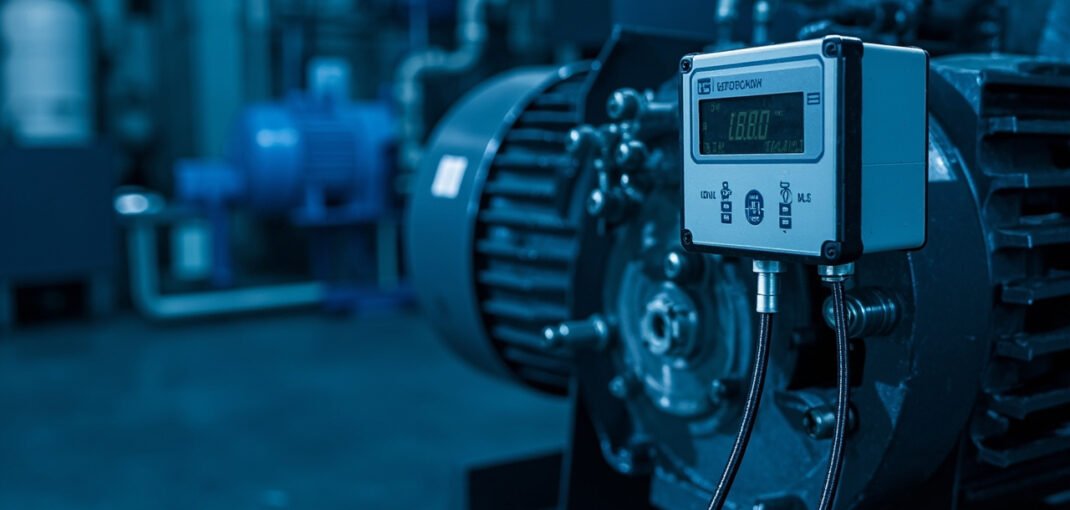
Predictive maintenance using vibration analysis is a critical decision for plant maintenance managers and reliability engineers aiming to prevent unplanned downtime and reduce maintenance costs. This article will help you calculate the return on investment for implementing vibration analysis, specify the appropriate sensors and monitoring systems, and design a phased rollout plan tailored to your plant’s needs.
Failure Modes Detected by Vibration Analysis and the Cost of Ignoring Them
Vibration analysis is a proven technique for detecting a range of mechanical faults in rotating machinery. Common failure modes include:
- Unbalance: Occurs when the center of mass does not coincide with the center of rotation, leading to excessive vibration.
- Misalignment: Happens when two rotating shafts are not properly aligned, causing increased stress and wear.
- Bearing faults: Include defects such as inner and outer race defects, ball or roller defects, and cage damage.
- Gear defects: Involve issues like tooth wear, pitting, and breakage.
- Looseness: Can be either structural or component-related, leading to increased vibration levels.
The cost of ignoring these faults can be significant. For instance, an unaddressed bearing fault can lead to catastrophic failure, resulting in extended downtime, costly repairs, and potential safety hazards. A study by the Society for Maintenance & Reliability Professionals (SMRP) found that unplanned downtime can cost industrial manufacturers up to $260,000 per hour. Early detection through vibration analysis can reduce these costs by up to 50%.
Physics of Vibration Analysis: Velocity and Acceleration
Vibration analysis relies on measuring the vibration velocity and acceleration of machinery. The primary formula for vibration velocity is:
v(t) = (dx(t)) / (dt)
where:
- v(t) is the velocity at time t
- x(t) is the displacement at time t
Acceleration is the rate of change of velocity:
a(t) = (dv(t)) / (dt)
Worked Example
Consider a motor with a rotational speed of 1800 RPM. The fundamental frequency f is:
f = (RPM) / (60) = (1800) / (60) = 30 Hz
If the displacement amplitude is 0.1 mm, the velocity amplitude V is:
V = 2π f x = 2π × 30 × 0.0001 = 0.0188 m/s
The acceleration amplitude A is:
A = (2π f)² x = (2π × 30)² × 0.0001 = 3.55 m/s²
Only the velocity figure is compared with the severity zones: ISO 10816-3 and its successor ISO 20816-3 define zones on RMS velocity, not on acceleration, and the boundaries depend on the machine group, the rigidity of the support and the rated speed.
ISO 10816 Severity Zones
| Zone | Meaning in the standard | Boundary values, mm/s RMS (Group 2, rigid support) | What maintenance does |
|---|---|---|---|
| A | Vibration of a newly commissioned machine | up to 1.4 | Record as the baseline |
| B | Acceptable for long-term operation | 1.4 to 2.8 | Keep the normal route interval |
| C | Not acceptable for long-term operation | 2.8 to 4.5 | Schedule investigation, shorten the interval |
| D | Likely to cause damage | above 4.5 | Stop the machine and investigate |
Group 2 measured on a flexible support gives 2.3 / 4.5 / 7.1 mm/s for the same three boundaries, and Group 1 machines on flexible supports sit at 3.5 / 7.1 / 11.0 mm/s. Take the row for your machine group and support type from the standard instead of copying a single set of numbers.
Selecting Between Route-Based and Continuous Monitoring
Sensor Type Selection Criteria
- Machine Criticality: High criticality machines justify permanent sensors.
- Accessibility: Difficult-to-access machines benefit from continuous monitoring.
- Cost: Balance the cost of sensors against the risk of failure.
- Environment: Harsh environments may require specialized sensors.
Comparison of Monitoring Methods
| Feature | Route-Based Monitoring | Continuous Monitoring |
|---|---|---|
| Cost | Lower | Higher |
| Frequency | Periodic | Real-time |
| Data Quality | Good | Excellent |
| Installation Complexity | Simple | Complex |
| Maintenance | Regular | Minimal |
Typical Machine Classes and Monitoring Strategies
| Machine Class | Monitoring Strategy |
|---|---|
| Critical Pumps | Continuous |
| Large Motors | Continuous |
| Small Motors | Route-Based |
| Gearboxes | Continuous |
| Fans | Route-Based |
Installation and Commissioning Procedure
Step-by-Step Installation
- Site Assessment: Evaluate the machine’s operating conditions and select appropriate sensor locations.
- Sensor Mounting: Attach sensors using magnetic mounts, adhesive, or threaded studs, ensuring solid contact.
- Wiring: Connect sensors to the data acquisition unit using shielded cables to minimize noise.
- Data Acquisition Unit Setup: Configure the unit according to the manufacturer’s guidelines, setting sampling rates and measurement ranges.
- Software Configuration: Install and configure the vibration analysis software, setting up measurement points and alarm thresholds.
- Initial Data Collection: Collect baseline data and verify signal quality.
- Alarm Threshold Setting: Use ISO 10816 zones to set initial alarm thresholds, adjusting as necessary based on historical data.
Commissioning Checklist
- Verify sensor placement and mounting integrity.
- Check wiring connections and signal quality.
- Confirm data acquisition unit settings.
- Validate software configuration and data collection.
- Test alarm thresholds with known vibration sources.
Ongoing Maintenance and Troubleshooting
Symptom and Probable Cause
- Increased Vibration Levels: May indicate imbalance, misalignment, or bearing wear.
- High Frequency Content: Suggests potential gear defects or bearing faults.
- Intermittent Peaks: Could point to looseness or intermittent contact.
Troubleshooting Steps
- Verify Sensor Integrity: Check for sensor damage or loose connections.
- Inspect Mounting: Ensure sensors are securely mounted.
- Check Wiring: Look for broken or shorted cables.
- Review Software Settings: Confirm configuration and data collection parameters.
- Analyze Data Trends: Look for patterns or anomalies in the vibration data.
Setting Inspection and Calibration Intervals
- Weekly: Quick visual inspection of sensors and wiring.
- Monthly: Detailed sensor check and data review.
- Quarterly: Comprehensive system audit and sensor recalibration.
Mounting, Data Quality and the Errors That Ruin a Vibration Reading
Proper mounting of vibration sensors is crucial for obtaining accurate and reliable data. The primary consideration is to ensure a direct and rigid connection between the sensor and the machine surface. Any air gap or loose attachment will introduce noise and distort the vibration signal. For instance, using a magnetic mount on a painted surface can lead to erroneous readings due to the damping effect of the paint layer. The recommended practice is to prepare the mounting surface by removing any coatings or rust and ensuring it is flat. The ideal mounting method is typically a threaded stud, which provides the most stable connection. For temporary measurements, a magnetic base can be used, but it should be verified that the magnetic force is sufficient to maintain constant contact.
The orientation of the sensor also plays a critical role in data quality. Vibration sensors are designed to measure movement in specific axes, and misalignment can result in cross-axis sensitivity errors. For example, a sensor intended to measure horizontal vibration should be mounted perpendicular to the surface with its axis aligned with the direction of interest. A misalignment of more than 5 degrees can introduce significant errors in the amplitude and phase of the vibration signal. Additionally, the cable connecting the sensor to the data acquisition system must be secured to prevent it from acting as an antenna for electromagnetic interference (EMI). Shielded cables are recommended, and they should be routed away from high-voltage lines and other sources of EMI.
Environmental factors can also impact data quality. Temperature variations can affect the sensitivity of the sensor, while high humidity can lead to corrosion of the mounting surface and the sensor itself. It is advisable to use sensors with a wide operating temperature range and to protect them from moisture with appropriate enclosures or coatings. Furthermore, the presence of dust and debris can interfere with the sensor’s operation, so regular cleaning and inspection are necessary. In environments with high levels of vibration or shock, it is important to use sensors with a high shock rating to prevent damage.
Turning Readings Into Action: Alarm Routes and Ownership
Once vibration data is collected, it must be translated into actionable information through a well-defined alarm system. The first step is to establish baseline vibration levels for each machine under normal operating conditions. These baselines serve as the foundation for setting alarm thresholds. ISO 10816 provides general guidelines for vibration severity, but it is often necessary to refine these based on the specific characteristics of the machinery and the operating environment. For example, a machine with a rotating speed of 1800 RPM might have a different acceptable vibration level compared to one operating at 3600 RPM.
Alarm routes should be designed to provide clear and immediate notification to the appropriate personnel. This typically involves setting up multiple alarm levels, such as warning, alert, and critical, each triggering a different response. For instance, a warning level might prompt a routine inspection, while a critical alarm would require immediate shutdown and repair. The alarm system should also be integrated with the plant’s maintenance management software to ensure that all alerts are logged and tracked. This helps in assigning ownership and accountability for each alarm, ensuring that corrective actions are taken in a timely manner.
The process of turning readings into action also involves regular review and analysis of the vibration data. This can be done through periodic reports or real-time dashboards that display key metrics such as overall vibration levels, frequency spectra, and trend analysis. Reliability engineers should be trained to interpret these data and to identify patterns that indicate potential issues. For example, an increasing trend in vibration amplitude at a specific frequency might suggest a developing fault in the machinery. By establishing clear alarm routes and ownership, plants can ensure that vibration data is effectively utilized to prevent failures and optimize maintenance activities.
Quick Selection Checklist
- Verify machine criticality and justify continuous monitoring.
- Assess accessibility and choose appropriate sensor type.
- Evaluate environmental conditions and select suitable sensors.
- Confirm data acquisition unit compatibility with sensors.
- Set up software for data collection and analysis.
- Establish baseline data and set alarm thresholds.
- Plan for regular maintenance and data review.
FAQ
How do I determine the optimal sensor placement?
Sensor placement should be based on the machine’s vibration characteristics and the type of fault you are trying to detect. Consult ISO 10816 and manufacturer guidelines for specific recommendations.
What is the typical lifespan of vibration sensors?
The lifespan varies depending on the environment and usage. Generally, expect 5-10 years with proper maintenance.
How often should I calibrate my sensors?
Calibration frequency depends on the sensor type and operating conditions. A general rule is to calibrate annually or after any event that may have affected the sensor.
Can vibration analysis detect all types of mechanical faults?
While vibration analysis is effective for many faults, it may not detect issues like electrical faults or corrosion. Combine it with other condition monitoring techniques for comprehensive coverage.
Specifying the Monitoring Hardware
Xiamen Lisen Trading Co., Ltd supplies vibration sensors, analysis modules and condition monitoring hardware for motors, pumps and fans. Tell us the machine class, bearing configuration and measurement points, and we will recommend sensor sensitivity, mounting stud and cable before quoting.
Related Vibration Sensors and Modules
- IFM VSA005 vibration sensor
- IFM VSE150 vibration analysis module
- HOUDE 8500B-WY812 axial displacement sensor