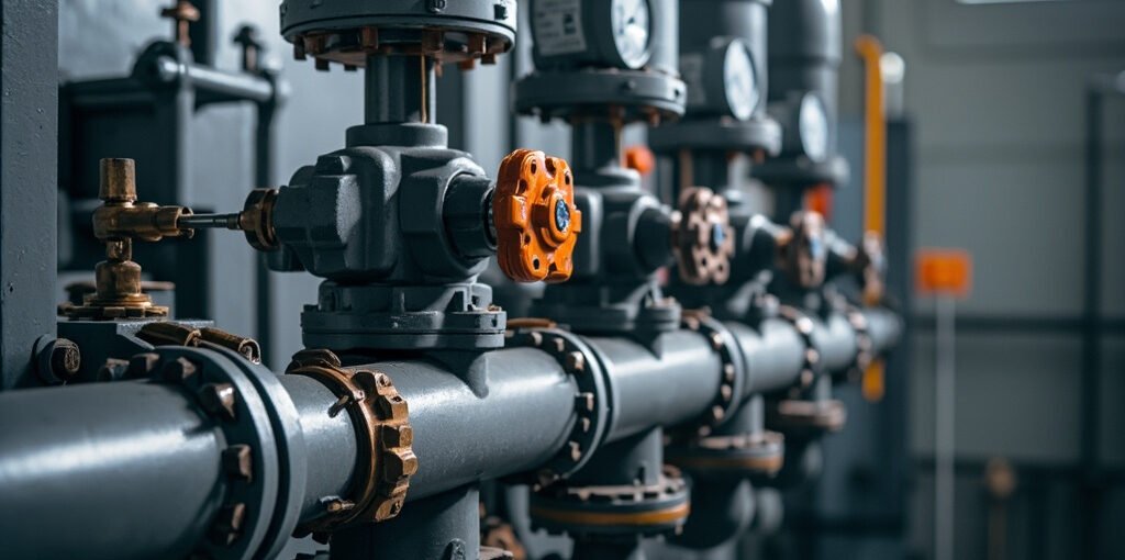
Industrial Gas Valve Train Leakage Testing: Comprehensive Guide to Safety and Reliability
Introduction
Industrial gas systems are integral to various manufacturing processes, power generation, and heating applications. Ensuring the safety and reliability of these systems is paramount, as any malfunction can lead to catastrophic consequences, including explosions and fires. Central to this safety is the gas valve train, which controls the flow of gas to burners and boilers. This article delves into the critical aspects of gas valve train leakage testing, focusing on tightness testing procedures, flame supervision electrode positioning, ignition sequence timing, and safety shut-off valve response time verification. We will also explore the role of specific products, such as the Kromschroder GFK 80F60-6 Gas Safety Shut-Off Valve, in ensuring optimal system performance and safety.
Gas Valve Train Components and Their Functions
1. Main Safety Shut-Off Valve
The main safety shut-off valve, such as the Kromschroder GFK 80F60-6 Gas Safety Shut-Off Valve, is a critical component designed to stop the gas flow in case of emergencies. It features a spring-return mechanism that ensures the valve closes automatically upon power loss, preventing uncontrolled gas release.
2. Pilot Valve
The pilot valve is a smaller capacity valve that establishes the pilot flame before the main valve opens. It is crucial for initiating the combustion process safely.
3. Gas Pressure Regulator
The gas pressure regulator maintains a constant downstream pressure, ensuring stable and efficient combustion. The Gas Pressure Monitoring Kromschroder KFM 100 RB 63 03 is an example of a device that provides accurate pressure regulation and monitoring.
4. Valve Proving System
The valve proving system monitors the tightness of the valves during standby periods. It checks for leaks by pressurizing the system and monitoring for pressure drops, ensuring the valves are sealing properly.
5. Flexible Connectors
Flexible connectors absorb thermal expansion and vibration, reducing stress on the valve train components and preventing leaks caused by mechanical stress.
6. Strainer
A strainer protects the valve seats from debris, ensuring smooth operation and preventing blockages that could lead to leaks or valve failure.
Tightness Test Procedure
1. Isolation of the Valve Train
Before conducting a tightness test, the valve train must be isolated between test points to ensure accurate results. This involves closing all relevant valves and ensuring no gas can escape during the test.
2. Pressurization
The system is pressurized to 1.5 times the maximum operating pressure using nitrogen or natural gas. This elevated pressure helps identify leaks that might not be apparent at lower pressures.
3. Monitoring Pressure Drops
A calibrated manometer with a resolution of 0.1 mbar is used to monitor pressure drops. The test duration varies depending on the system size:
- Small Systems: Minimum of 5 minutes
- Large Systems: Minimum of 10 minutes
4. Acceptable Leak Rates
- Safety Shut-Off Valves: Zero leakage per EN 161 (Class A)
- Regulating Valves: <0.1% of rated flow per EN 746-2
5. Temperature Considerations
Ambient temperature is recorded during the test, as pressure can vary with temperature. This ensures that any fluctuations in pressure are not misinterpreted as leaks.
Flame Supervision Electrode Positioning
Proper positioning of flame supervision electrodes is crucial for reliable flame detection. The UV flame detector, such as the UV Flame Detector Kromschroder FDU 510 W0T2/1O1-0K1, must have a clear line of sight to the flame. The following guidelines apply:
- Mounting Angle: 45-degree angle to the burner nozzle
- Distance from Nozzle: 3-5 times the nozzle diameter
- Response Time: Detector should respond within 1 second of flame ignition
- Maintenance: Clean the detector window quarterly to remove carbon deposits that reduce UV sensitivity
For ionization electrodes, positioning is equally important:
- Position: In the flame root (stable ionization zone)
- Gap: 3-5mm
- Signal Current: >2 microA
Ignition Sequence Timing
The ignition sequence must adhere to strict timing to ensure safe and reliable ignition. The EN 298 burner control sequence is as follows:
| Step | Description | Duration |
|---|---|---|
| 1 | Pre-purge | 30 seconds (natural gas), 60 seconds (LPG) |
| 2 | Pilot valve opens, ignition transformer energized | – |
| 3 | Pilot flame proven | Within 3 seconds |
| 4 | Main valve opens | 1-2 seconds after pilot proven |
| 5 | Lockout and alarm if flame not proven | Within 1 second at any stage |
The total safety time from fuel release to flame proof should be less than 5 seconds. This ensures that any failure in the ignition process triggers a rapid shutdown, preventing gas accumulation and potential explosions.
Safety Shut-Off Valve Response Time Verification
The response time of safety shut-off valves is critical for system safety. The closing time is measured from the moment power is cut off to when the valve is fully closed. The following standards apply:
- Valve Sizes up to DN100: Closing time <1 second
- Valve Sizes DN100-DN200: Closing time <2 seconds
The measurement is performed using a pressure transducer downstream of the valve. The pressure must drop to less than 10% of the operating pressure within the specified closing time. If the closing time exceeds these specifications, the following checks should be performed:
- Spring Return Mechanism: Verify functionality
- Valve Seat: Check for debris or damage
- Valve Condition: Replace if worn
Valve Proving System Operation
The valve proving system operates after the main valve closes at the end of the firing cycle. The process involves:
- Test Port Opening: The test port downstream of the main valve is opened.
- Pressure Monitoring: The system monitors for any pressure rise, which would indicate valve leakage.
- Lockout and Alarm: If the pressure rises above a certain threshold, the system triggers a lockout and alarm.
- Test Duration: The test lasts between 30-60 seconds.
- Re-attempt: The valve proving must pass before the next start attempt.
- Inspection: If the proving fails, the valve seat should be inspected for debris or damage.
Periodic Maintenance Schedule
Regular maintenance is essential for the reliable and safe operation of gas valve trains. The following schedule is recommended:
- Monthly:
- Visual inspection of the valve train
- Check for gas odor
- Verify flame pattern
- Quarterly:
- Tightness test
- Flame supervision electrode cleaning
- Check strainer
- Annually:
- Full functional test of all safety devices
- Valve response time measurement
- Replace flexible connectors after 10 years
- Every 5 Years:
- Hydrostatic test of gas piping
- Replace safety shut-off valve internals per manufacturer schedule
Common Safety Violations and Their Consequences
Several common safety violations can compromise the integrity of gas valve trains:
- Bypassing Flame Supervision System: This is immediately dangerous as it removes a critical safety layer, increasing the risk of gas accumulation and potential explosions.
- Using Incorrect Gas Type Without Re-jetting Burner: Different gases have different combustion properties. Using the wrong gas type without re-jetting the burner can lead to unstable combustion and increased risk of fire.
- Operating with Known Gas Leak: Operating with a known gas leak is an explosion risk and should be addressed immediately.
- Skipping Pre-purge Timer Adjustment: Incomplete purging can leave residual gas, leading to unstable combustion and potential explosions.
- Using Non-rated Flexible Connectors: Non-rated connectors may not withstand the operating conditions, leading to leaks and system failure.
- Mounting Safety Shut-Off Valve in Wrong Orientation: The orientation affects the functionality of the spring return mechanism, which is crucial for emergency shutdowns.
- Ignoring Gas Pressure Regulation: Over-pressure can cause unstable combustion, leading to increased risk of fire and equipment damage.
Flame Supervision Comparison Table
| Feature | UV Flame Detector | Ionization Electrode |
|---|---|---|
| Principle | Detects UV radiation from flame | Measures ionization current in flame |
| Response Time | 1 second | 2-3 seconds |
| Sensitivity | High | Moderate |
| Maintenance | Quarterly cleaning | Regular inspection |
| Cost | Higher | Lower |
| Application | General purpose | Specific applications |
Ignition Sequence Timing Reference Table
| Step | Description | Duration |
|---|---|---|
| 1 | Pre-purge | 30 seconds (natural gas), 60 seconds (LPG) |
| 2 | Pilot valve opens, ignition transformer energized | – |
| 3 | Pilot flame proven | Within 3 seconds |
| 4 | Main valve opens | 1-2 seconds after pilot proven |
| 5 | Lockout and alarm if flame not proven | Within 1 second at any stage |
FAQ Section
1. What is the purpose of the valve proving system?
The valve proving system ensures the tightness of the valves by checking for leaks after the main valve closes. This is crucial for preventing gas accumulation and potential explosions.
2. How often should the flame supervision electrodes be cleaned?
The flame supervision electrodes should be cleaned quarterly to remove carbon deposits that can reduce UV sensitivity and compromise flame detection.
3. What is the acceptable leak rate for safety shut-off valves?
The acceptable leak rate for safety shut-off valves is zero leakage per EN 161 (Class A).
4. What is the response time of the Kromschroder GFK 80F60-6 Gas Safety Shut-Off Valve?
The Kromschroder GFK 80F60-6 Gas Safety Shut-Off Valve has a closing time of less than 1 second for valve sizes up to DN100, ensuring rapid response in case of emergencies.
5. What is the role of the Gas Pressure Monitoring Kromschroder KFM 100 RB 63 03?
The Gas Pressure Monitoring Kromschroder KFM 100 RB 63 03 maintains a constant downstream pressure, ensuring stable and efficient combustion.
Conclusion
The safety and reliability of industrial gas systems depend on the proper functioning of the gas valve train and flame supervision systems. Regular testing, maintenance, and adherence to safety standards are essential for preventing accidents and ensuring optimal system performance. By understanding the intricacies of tightness testing, flame supervision electrode positioning, ignition sequence timing, and safety shut-off valve response time verification, operators can significantly enhance the safety and efficiency of their gas systems.
Call to Action
Explore our range of industrial gas system components, including the Kromschroder GFK 80F60-6 Gas Safety Shut-Off Valve, Boiler Gas Valve Kromschroder VG 15/12 R18NK31 85265200, and Gas Pressure Monitoring Kromschroder KFM 100 RB 63 03, to ensure your gas systems are equipped with the highest quality components. Visit our website to browse our full product catalog and find the solutions you need for your industrial applications.