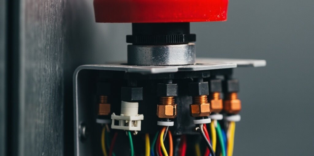
Emergency stop wiring is one of the most critical aspects of industrial machine safety design. Whether you are an electrical engineer, a maintenance technician, or a machine builder, understanding how to properly wire an emergency stop (E-stop) circuit can mean the difference between a safe operation and a catastrophic workplace accident. This comprehensive guide covers everything you need to know about emergency stop wiring, from fundamental principles and global safety standards to step-by-step wiring procedures, color codes, component selection, and best practices for reliable fail-safe operation.
An emergency stop is a failsafe control device designed to immediately halt a machine or process during an emergency. According to international standards, the emergency stop function must be always available, always operational, and able to override all other commands. The wiring of this circuit must reflect these non-negotiable safety requirements through the use of positive-break contacts, redundancy, and self-monitoring logic.
Why Emergency Stop Wiring Matters in Industrial Safety
Industrial machinery operates at high speeds, with powerful actuators, and often in environments where human operators are in close proximity. When something goes wrong—a jam, a mechanical failure, a human error, or a foreign object entering the work envelope—every millisecond counts. A properly wired emergency stop circuit provides the immediate means to remove power from hazardous motion, stop moving parts, and bring the system to a safe state.
Improperly wired E-stop systems can result in delayed shutdowns, failure to stop, or inadvertent machine restarts—all of which contribute to workplace injuries, fatalities, regulatory fines, and costly litigation. For this reason, regulatory bodies worldwide enforce strict compliance with standards such as ISO 13850, IEC 60947-5-5, and NFPA 79.
Key Global Standards for Emergency Stop Wiring
Before diving into wiring techniques, it is essential to understand the regulatory framework that governs emergency stop design. The table below summarizes the most important international standards.
| Standard | Region / Scope | Primary Focus |
|---|---|---|
| ISO 13850 | International | Design and functional requirements for emergency stop devices |
| IEC 60947-5-5 | International | Low-voltage switchgear – Emergency stop devices |
| NFPA 79 | United States | Electrical standard for industrial machinery |
| EN 60204-1 | Europe | Electrical equipment of machines – General requirements |
| ANSI/RIA R15.06 | United States (Robots) | Industrial robot safety requirements |
Core Components of an Emergency Stop Circuit
An effective emergency stop wiring system relies on the careful integration of several hardware components. Each plays a vital role in ensuring a fail-safe response when the E-stop is activated.
- E-Stop Pushbutton (Mushroom-Head Switch): A red mushroom-headed button on a yellow background, required by ISO 13850. It must use a positive-opening (force-guided) mechanism that physically breaks the contacts even if the spring fails.
- Safety Contactor or Power Relay: The actual switching device that interrupts power to motors, actuators, or control circuits. Must be a force-guided contactor for safety monitoring.
- Safety Relay or Safety Controller: A device that monitors the E-stop circuit for faults such as welded contacts, broken wires, or short circuits. Examples include Pilz PNOZ, Allen-Bradley Guardmaster, and Siemens 3SK.
- Normally Closed (NC) Contacts: Used on the E-stop button so that when pressed, the circuit opens. Two NC contacts are typically wired in series to provide redundancy.
- Reset / Acknowledge Pushbutton: After the E-stop is released, this button must be pressed to restart the machine—preventing automatic restart.
Step-by-Step Emergency Stop Wiring Procedure
Below is a generalized procedure for wiring a Category 1 or Category 3 emergency stop circuit. Always refer to manufacturer documentation and applicable local codes before performing any electrical work.
Step 1 – Disconnect and Lock Out All Power
Before touching any wiring, isolate the machine from its power source using a lockout/tagout (LOTO) procedure. Verify zero energy with a properly rated voltage tester.
Step 2 – Mount the E-Stop Pushbutton
Install the mushroom-head E-stop button in an easily accessible location at each operator station. ISO 13850 requires it to be placed at every control station and at points where an emergency may occur.
Step 3 – Wire the NC Contacts to the Safety Relay
Connect both NC contacts of the E-stop button in series to the input terminals of the safety relay. Most safety relays have dual-channel inputs (Channel 1 and Channel 2) to detect cross faults.
Step 4 – Connect the Safety Contactor
Wire the output of the safety relay to the coil of the safety contactor. The contactor’s power contacts will be installed in series with the motor or actuator supply lines.
Step 5 – Add a Reset Circuit
Install a normally open (NO) reset pushbutton on a separate terminal. The safety relay will only re-energize the contactor after both the E-stop is released and the reset button is pressed.
Step 6 – Test the System
Activate the E-stop and verify that the contactor drops out within milliseconds. Release the button and confirm that the system does not restart automatically—only after a deliberate reset.
Wire Color Codes for Emergency Stop Wiring
Color coding helps technicians quickly identify safety circuits during installation, troubleshooting, and maintenance. While local standards vary, the following color conventions are widely accepted.
| Wire Function | Recommended Color | Notes |
|---|---|---|
| E-Stop Circuit (24 VDC) | Red / Yellow | High visibility for safety |
| Safety Relay Outputs | Orange | Distinguishes from standard I/O |
| Reset Circuit | Blue | Indicates acknowledge / manual function |
| Protective Earth (PE) | Green/Yellow | Per IEC 60446 |
Common Mistakes to Avoid in Emergency Stop Wiring
- Using a single-channel E-stop circuit: Without redundancy, a single contact weld can render the E-stop useless. Always use dual-channel wiring.
- Wiring the E-stop in series with a PLC output: The PLC must never be the sole means of stopping the machine. The E-stop must directly interrupt power.
- Skipping the manual reset: Auto-reset can cause unexpected machine startup, endangering nearby personnel.
- Using standard contactors instead of force-guided ones: Standard contactors cannot be monitored for welded contacts, defeating the purpose of dual-channel monitoring.
- Placing the E-stop button in hard-to-reach locations: ISO 13850 requires it to be reachable from every operator position and hazard zone.
⚠ Critical Safety Warning: Never use a programmable logic controller (PLC) as the only safety device in an E-stop circuit. PLCs can fail, lock up, or have scan-time delays of up to 100 ms or more. Always use a certified safety relay, safety controller, or contactor-based circuit that can directly interrupt