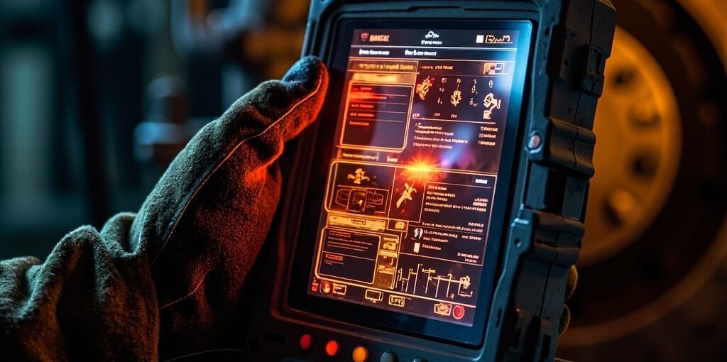
Industrial robot teach pendants serve as the primary interface between operators and robotic systems in manufacturing environments. These handheld control devices enable programmers to manually guide robots through positions, program routines, and troubleshoot operational issues. When a teach pendant malfunctions or experiences issues, it can bring entire production lines to a standstill, resulting in significant downtime costs and scheduling disruptions. Understanding the common problems that affect teach pendants, their underlying causes, and effective troubleshooting strategies is essential for maintenance technicians, robotics engineers, and production supervisors who rely on these critical pieces of equipment to maintain smooth manufacturing operations.
Common Industrial Robot Teach Pendant Issues
Teach pendants face harsh operating conditions in industrial settings, including exposure to dust, coolant, vibrations, and frequent handling by multiple operators. These environmental factors contribute to several recurring problems that maintenance teams encounter regularly. The most frequently reported issues fall into several distinct categories, each requiring specific diagnostic approaches and resolution strategies.
Physical Damage and Wear
Physical damage represents one of the most prevalent causes of teach pendant failures in industrial environments. The pendant’s emergency stop button may become unresponsive due to accumulated debris or worn mechanical components beneath the protective housing. Cable connections between the pendant and the robot controller frequently experience wear at the strain relief points, leading to intermittent connectivity or complete signal loss. The pendant’s display screen can suffer from cracked LCD panels when dropped or struck by heavy objects, while the protective rubber boot may develop tears that allow coolant and metal chips to penetrate the internal electronics. Touchscreen calibration drift occurs when the display’s digitizer loses its original alignment, causing input inaccuracies that make precise robot positioning difficult or impossible.
⚠ WARNING: Never attempt to open or repair a teach pendant while the robot system remains powered on. Always isolate electrical power sources before conducting any internal inspection or component replacement to prevent severe electrical shock and equipment damage.
Communication and Connectivity Problems
Network communication issues between the teach pendant and the robot controller manifest through various symptoms including slow response times, failed program uploads, and error messages indicating communication timeouts. These problems often originate from damaged Ethernet cables, loose connections at the controller cabinet, or corrupted communication settings within the robot’s configuration parameters. In systems using proprietary communication protocols, firmware version mismatches between the pendant and controller can prevent successful handshaking, leaving operators unable to execute basic commands or access the teach pendant’s interface functions.
Technical Troubleshooting Methods
Effective troubleshooting of teach pendant issues requires a systematic approach that eliminates potential causes methodically while documenting each diagnostic step for future reference. Maintenance personnel should establish a consistent troubleshooting workflow that begins with visual inspections before proceeding to more invasive diagnostic procedures.
Initial Diagnostic Procedures
Begin every troubleshooting session with a thorough visual inspection of the entire teach pendant assembly. Examine the external housing for cracks, missing screws, or signs of liquid ingress that might indicate deeper internal problems. Check all cable connections for secure seating and inspect cable jackets for visible damage such as cuts, abrasions, or chemical degradation. Verify that the emergency stop button resets properly and that all indicator lights illuminate when the system powers up. Document any error codes displayed on the pendant screen, as these diagnostic codes provide valuable clues about underlying system faults that may not be immediately apparent through physical inspection alone.
- Verify power supply voltage levels at the controller cabinet terminals
- Test cable continuity using a multimeter on all signal wires
- Check Ethernet port link lights for proper network connectivity
- Compare current firmware versions against manufacturer specifications
- Reset teach pendant to factory defaults as a baseline diagnostic step
Display and Interface Troubleshooting
When the teach pendant display fails to show information correctly, technicians must determine whether the problem originates from the display hardware itself or from software configuration issues. A completely black screen may indicate a failed backlight inverter, damaged display ribbon cables, or complete loss of power to the unit. Flickering displays often result from failing power supplies or loose ribbon cable connections within the pendant housing. Touchscreen unresponsiveness typically stems from calibration drift, damaged digitizer components, or interference from protective screen covers containing metallic layers.
| Display Symptom | Possible Causes | Recommended Actions |
|---|
| No display output | Power failure, backlight issues, cable damage | Check power supply, inspect cables, test backlight voltage |
| Flickering screen | Loose connections, failing inverter, EMI interference | Reseat ribbon cables, replace inverter, check grounding |
| Touch not registering | Calibration error, digitizer failure, debris buildup | Recalibrate touchscreen, clean surface, replace digitizer |
| Partial display visible | Damaged LCD panel, failed driver circuit | Replace LCD assembly, repair driver board |
Button and Switch MalfunctionsThe physical buttons on a teach pendant experience thousands of actuations during normal operation, making mechanical wear a significant concern over time. Dead button syndrome occurs when specific keys fail to register inputs, often due to worn conductive rubber contacts or accumulated contamination beneath the button caps. Toggle switches may develop intermittent behavior where they function correctly during some operations but fail during others, indicating partial internal contact degradation that will eventually result in complete failure.Emergency Stop System Failures
The emergency stop circuit represents a critical safety system that must function reliably under all circumstances. When the emergency stop button fails to trigger the safety chain or becomes difficult to actuate, it poses serious risks to personnel and equipment. Common causes include broken return springs inside the E-stop mechanism, corroded contacts in the mushroom head assembly, or wiring faults in the safety circuit that prevent proper signal transmission to the robot controller. Any malfunction of the emergency stop system requires immediate attention and should not be bypassed or worked around, as this violates occupational safety regulations and industrial standards governing robotic installations.- Test the E-stop circuit by pressing the button and verifying the safety chain status on the controller diagnostic screen
- Inspect the mushroom head for cracks, deformation, or signs of physical damage that might impede proper operation
- Check return spring tension by comparing the button’s reset force against manufacturer specifications
- Verify wiring integrity at all connection points within the safety circuit using appropriate testing equipment
- Replace components that show signs of wear or fail functional testing with manufacturer-approved replacement parts
Software and Firmware Complications
Modern teach pendants rely heavily on embedded software and firmware to manage their extensive functionality. Outdated firmware versions may contain bugs that cause unexpected behavior, while corrupted software installations can render the pendant completely inoperable. Understanding how to manage software updates and recover from firmware corruption is essential knowledge for anyone responsible for maintaining robotic systems.Firmware Update Failures
Attempted firmware updates sometimes fail midway through the installation process, leaving the teach pendant in an unusable state between the old and new software versions. This situation typically occurs when the update process is interrupted by power loss, cable disconnection, or network interruptions during the transfer. Most robot manufacturers provide recovery procedures using boot loader modes that allow technicians to reinstall firmware through alternative methods. Always verify the integrity of firmware files before initiating updates and ensure stable power and communication connections throughout the entire installation process.Preventive Maintenance Recommendations
Implementing a regular preventive maintenance schedule significantly reduces the frequency of teach pendant failures and extends the operational lifespan of these devices. Establishing maintenance protocols that address both physical protection and electronic reliability ensures maximum uptime and minimizes unexpected production interruptions.| Maintenance Task | Frequency | Key Benefits |
|---|
| Visual inspection and cleaning | Weekly | Early detection of damage, prevents contamination issues |
| Cable connection verification | Monthly | Prevents intermittent connectivity problems |
| Touchscreen calibration check | Quarterly | Maintains input accuracy and operational precision |
| Firmware update assessment | Semi-annually | Addresses known bugs, improves system stability |
| Complete functional testing | Annually | Comprehensive reliability verification |
When Professional Service Is Required
Certain teach pendant issues exceed the scope of routine maintenance and require intervention from qualified service technicians with specialized training and diagnostic equipment. Printed circuit board repairs, LCD panel replacements, and complex communication troubleshooting often demand manufacturer-certified repair services that possess the technical expertise and access to genuine replacement components necessary for proper restoration. Attempting advanced repairs without appropriate training risks causing additional damage, voiding warranties, and creating safety hazards that could endanger maintenance personnel and production workers alike.The investment in regular preventive maintenance, combined with prompt attention to developing issues, delivers substantial returns through improved equipment reliability, reduced emergency repair costs, and minimized production downtime. By understanding the common failure modes affecting industrial robot teach pendants and implementing systematic troubleshooting and maintenance procedures, maintenance teams can ensure these critical control interfaces continue functioning reliably throughout their operational lifespan.